11 images are available.

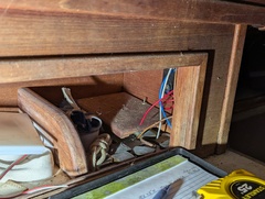


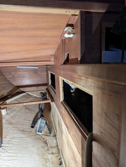

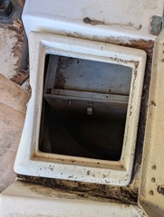
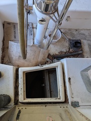
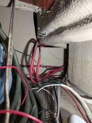
These photos are somewhat important to me for planing wire runs in the boat. The first is where the old breaker panel went. Wire access is terrible there. The second, third, and fourth are the inside of the small locker behind the top of the companionway stairs (right to left). This leads from about where the old breaker box was to the other side of the stairs. There is currently a bilge pump switch there. The fifth is the panel where the high amperage breaker panel will go. The sixth is looking up and an area below the cockpit seat where solenoids and shunts can be mounted. The seventh is is looking back into the pilot berth area. The empty space under the berth was created by removing the diesel tank. The large rectagular holes were for engine access. The small square hole serves no purpose. The sloping ceiling creates a cavity which may come in handy for running wires. The eight is the front of the forward starboard side cockpit locker. The ninth is the is the locker behind that looking at the back of the enclosure around the pilot berth. There is a false ceiling in that pilot berth enclosure which may prove useful for running wires. The tenth is the same locker taken from further back. The eleventh and final photo is looking forward from inside in an attempt to figure out what is holding some of the wires that run forward to the old breaker box and over the ice box to where the alternator used to be. It appears the structure on the left was glassed in after wires were installed hidine wire ties that are keeping the wires in place. That structure is the chute from the cockpit where ice could be dropped into the icebox (quite a distance so apparently never used as the ice box would be dented).
11 images are available.